To finish of our Engineering class, we built a final project, a lightsculpture. I built a disco ball hook.
The Idea
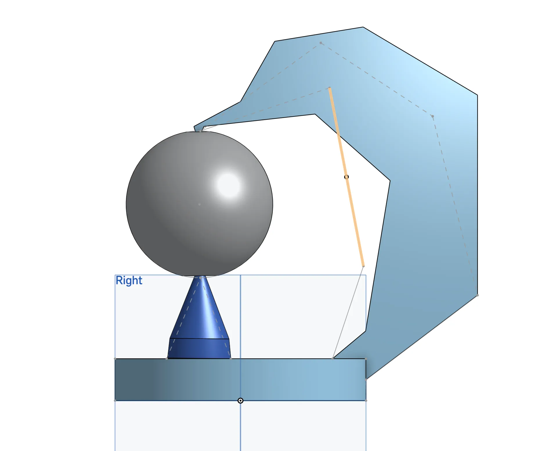
My idea for the disco ball hook was inspired by floating disco balls that you can see in some movies that happened during the 70s and the Las Vegas Sphere. For lighting, I wanted a hook that that would go up and over a ball, my intial sketch can be seen in the right. A Hook that loops over the ball and also a cone that goes from under the ball. This way the ball is hooked. I also wanted to have LEDs that shone inside the ball and also up along the arm. My plan was to use a custom pcb along with translucent 3d print to have diffused lighting.
The Cadding Process
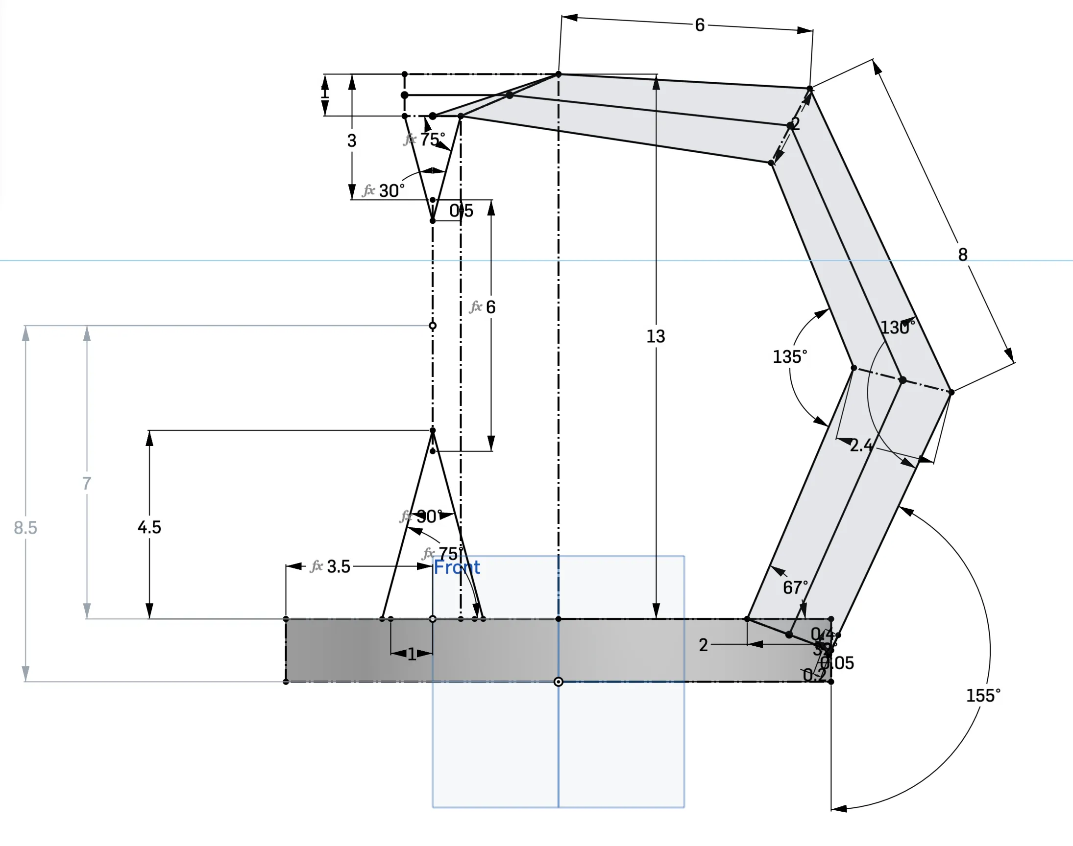
Overall the Cadding process was quite easy. I was already proficient with cad before the class and with the CADing unit, I had it down. I started by taking my initial idea and making a rough sketch on Onshape to get everything planned out. As such I used one singular sketch that defined everything my project was going to do. My sketch can be seen on the right. As you can see, I defined the profile of my light sculpture and everything else on the cad and the sculpture was based of this sketch. Another Important thing that I did was to do all my light sculpture inside one part studio. This is the way that Onshape designed and its what makes Onshape special to other CAD programs. Using one part studio allows me to design my whole light sculpture and ensure that everything connects instead of spending time assembling it on a Assembly just to find out that something doesn't work.
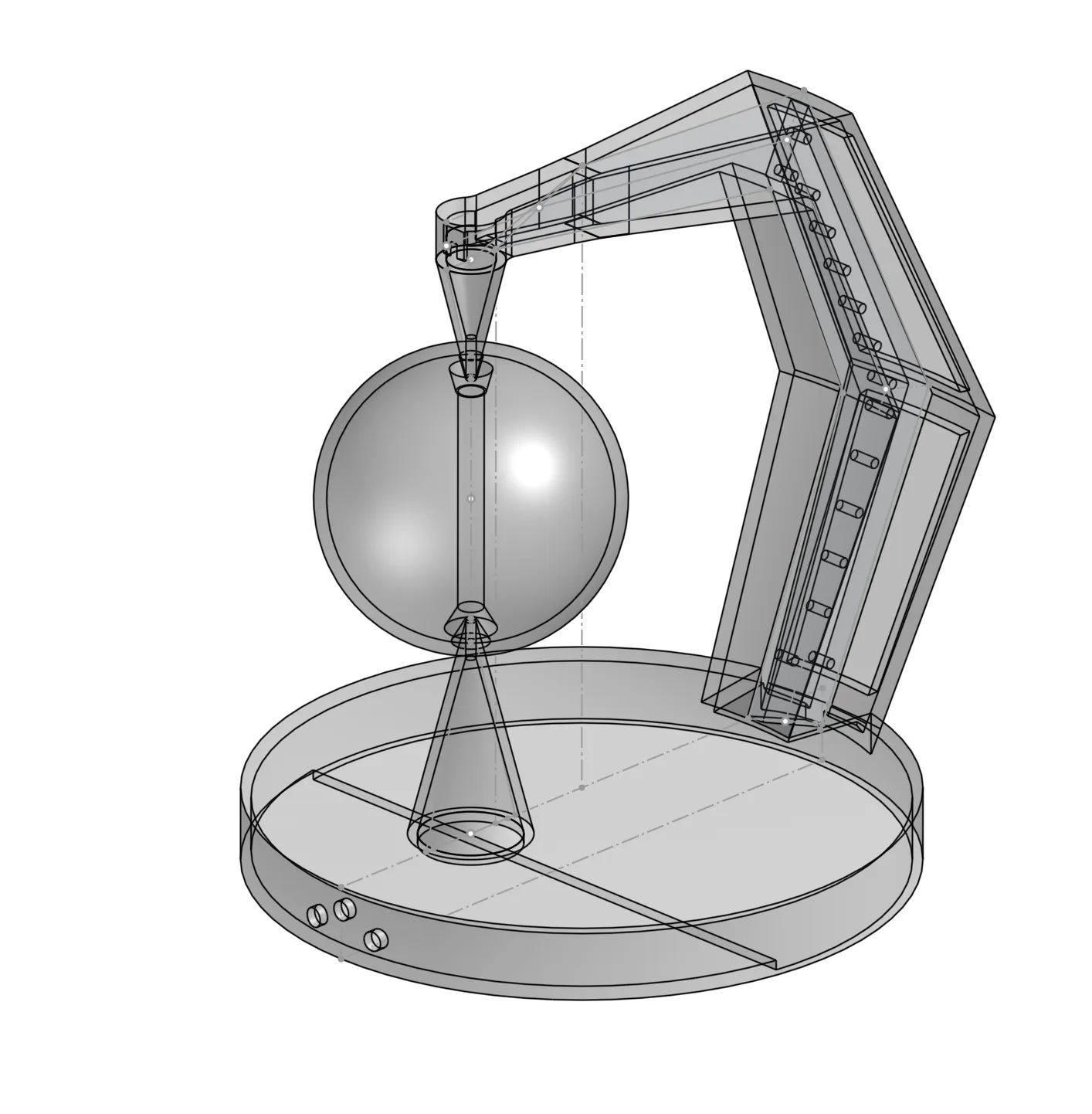
Here on the right is my first final draft of my CAD. It is through this that I started 3d printing parts and even though it would change, this was 90% complete. In the picture you can see that everything was transparent because I wanted the diffused lighting and the translucent 3d print. My intial plan was to 3d print this whole thing as one part. But I would later find that not possible as my part was to big for the 3d printer leading me to break the parts down. Also notice that my CAD at this time still planned on using LEDs, I had not already started on working on the PCB.
Manufacturing (PCB and 3d Printing)
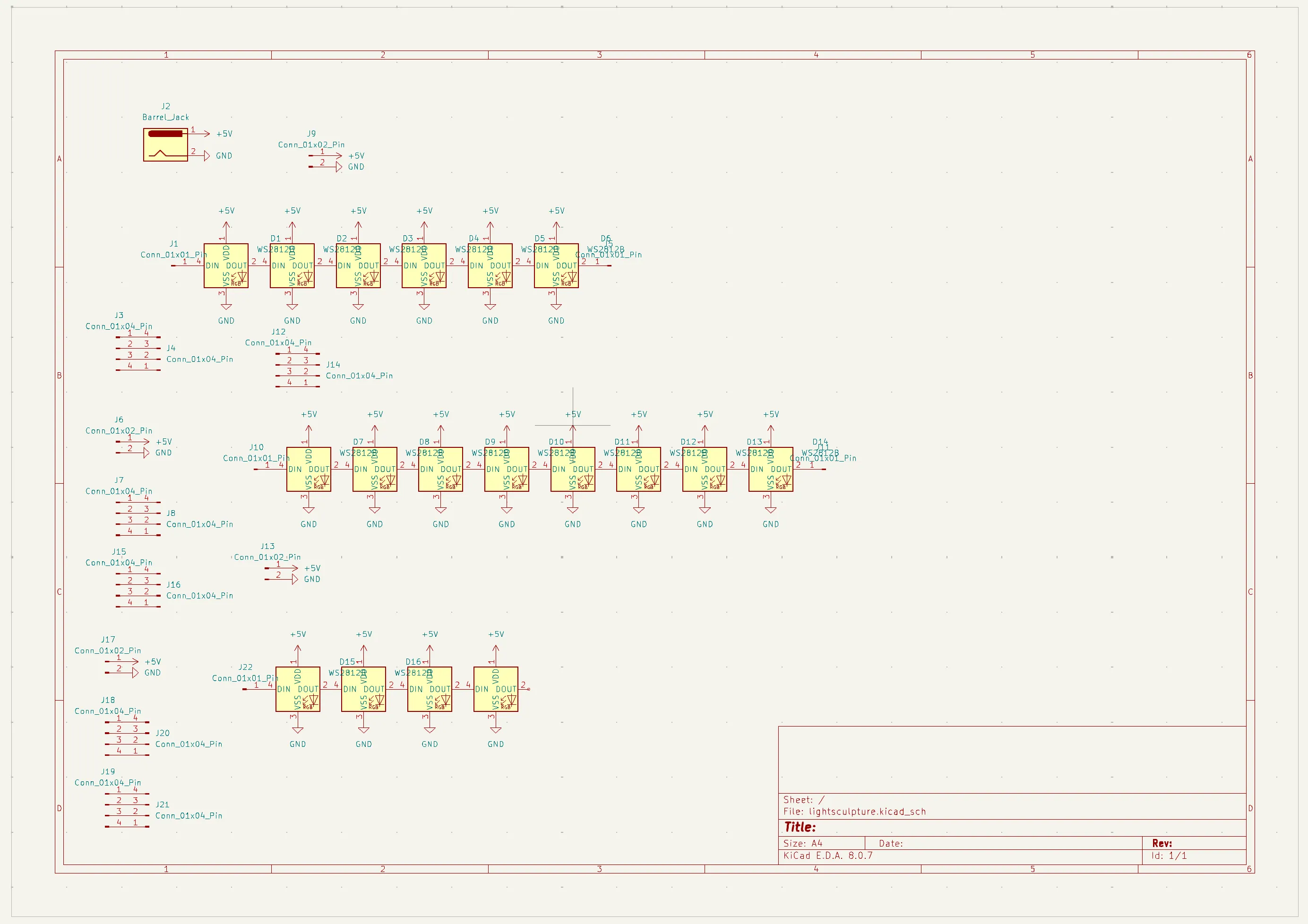
Here on the left, you can see my schematic of a pcb that I decided to design. I did this because I wanted to have rgb lights so I can determine what color the CAD is. So instead of the 5mm LEDs that most used, I ended up using 18 WS2182B LEDs that was integrated into my PCB. Along the way I had to learn KiCad, a program for making PCBs which was very interesting but I can also see that it will help me in the future.
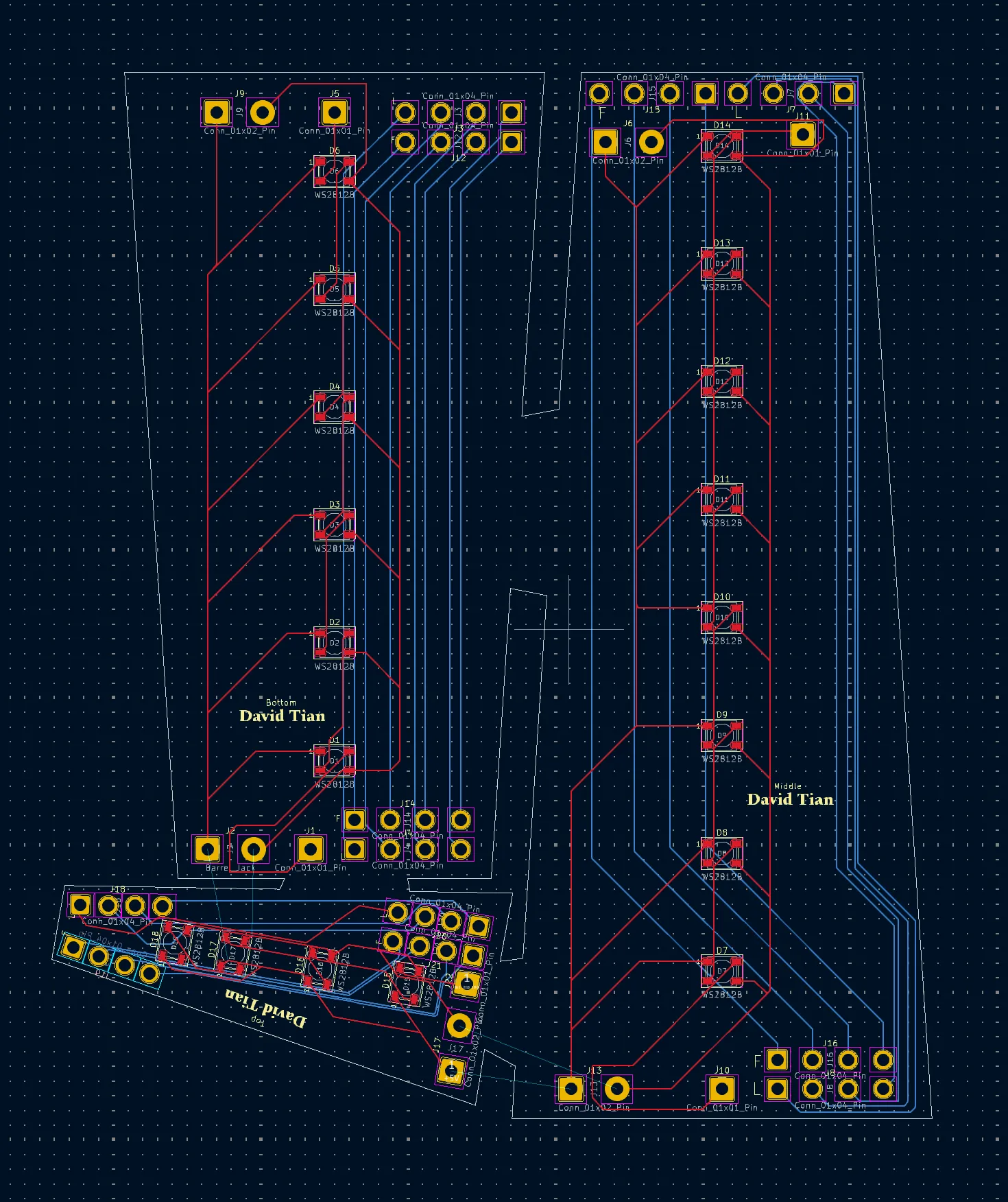
Here is the PCB tab of KiCad. In the schematic tab (the image above), you are making your schematic, but your board is not actually defined there. It is here in the pcb tab that you design your layout. So here you can see in the white line, the layout of the exact size that I needed my board to be. This is supposed to be three boards but as you can see, it is all connected, which allows me to save 20 dollars as the pcb manufacturer will charge me more if I move than one board. I ended paying $71 for my pcb, though most of it was actually shipping whereas only $30 dollars was making it.
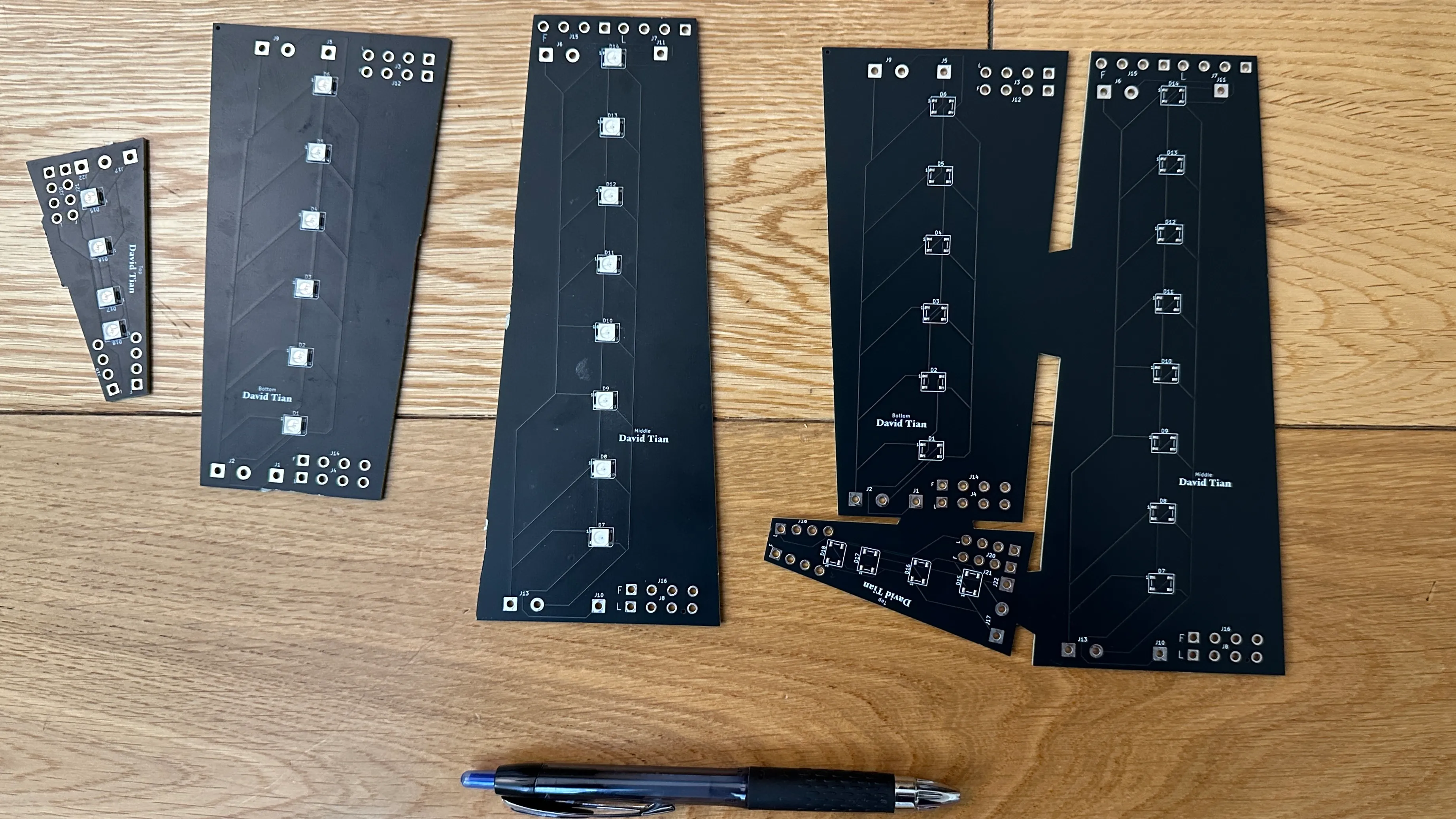
Above you can see my final PCB that was ordered. The physical is basically made based of the PCB that I designed in KiCad. On the left, I have one set of the board with the LEDs that were soldered on and where I had already sawed the parts into the 3d parts that I need it to be. On the right you can see the board as it was cut, it is still in one piece.
For the rest of my project, I ended up 3d printing. I have a couple timelapses of the parts 3d printing. Here are are them below.
Soldering
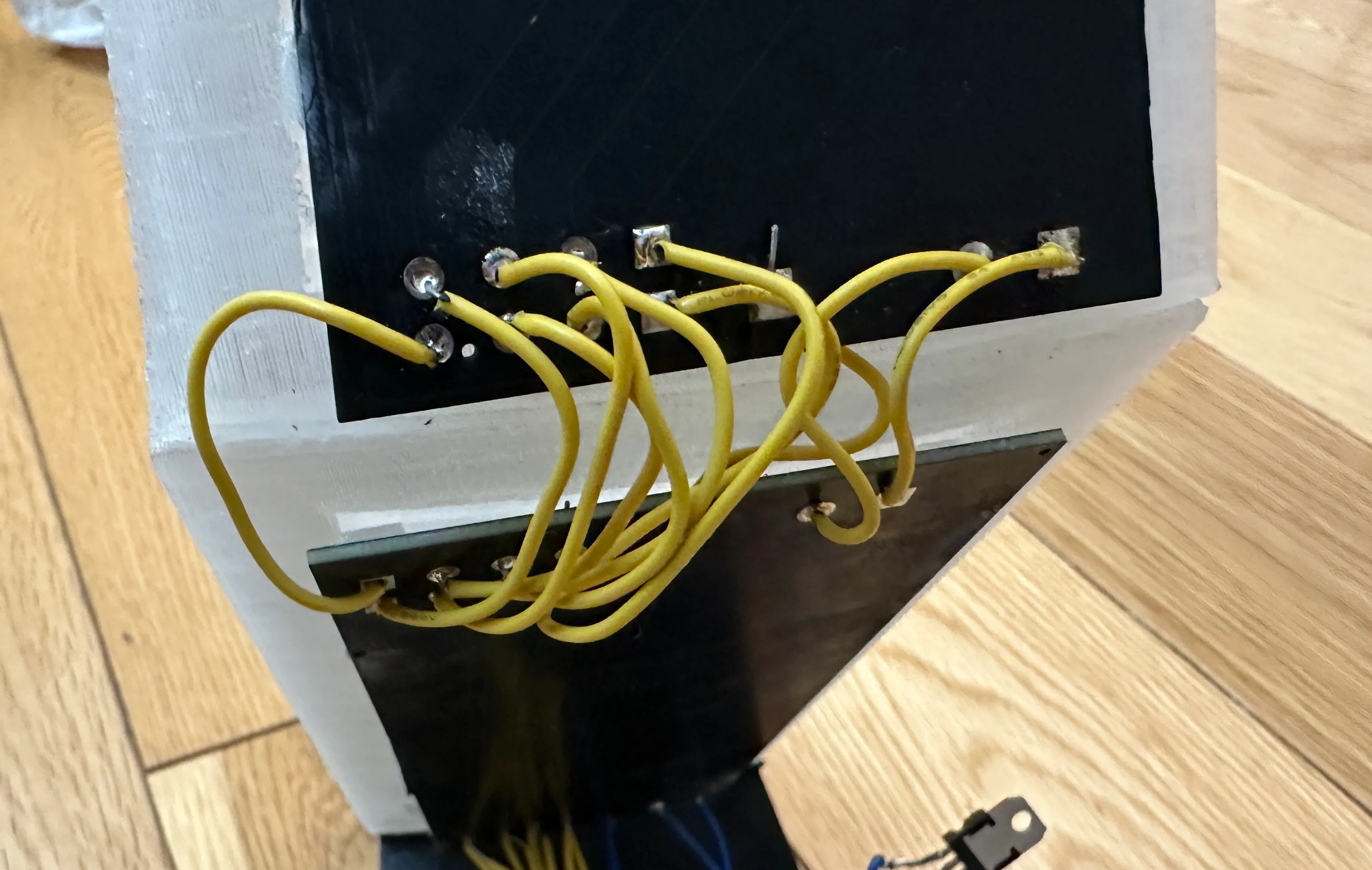
Because I did most of electronics in a PCB, it means that I did not have much to solder. I did have to solder my boards together. I had purposely designed holes inside my PCB that allows me to solder wire through it, kind of like how a perfboard is. It was not difficult and on the left I have an image of an example of the connections between boards that I ended up soldering.
Below I have an video of me soldering my part. What I am doing here is working on soldering the voltage regulator for my project. This ensures that there is correct voltage that is feeding into my pcb to ensure that it does not burn out. Overall soldering was relative simple because I already have experience with it.
Assembly and Final Part and Programming
To assemble my part, I used Gorrila superglue to connect the pieces that I printed into one final part. The proccess was simple, first sand down the edge so that there is a surface for it to grip, then apply some glue (I might of over done it) and then hold it together for only a couple minutes before it set and it was good to go. Here on the left is part of my assembly process.
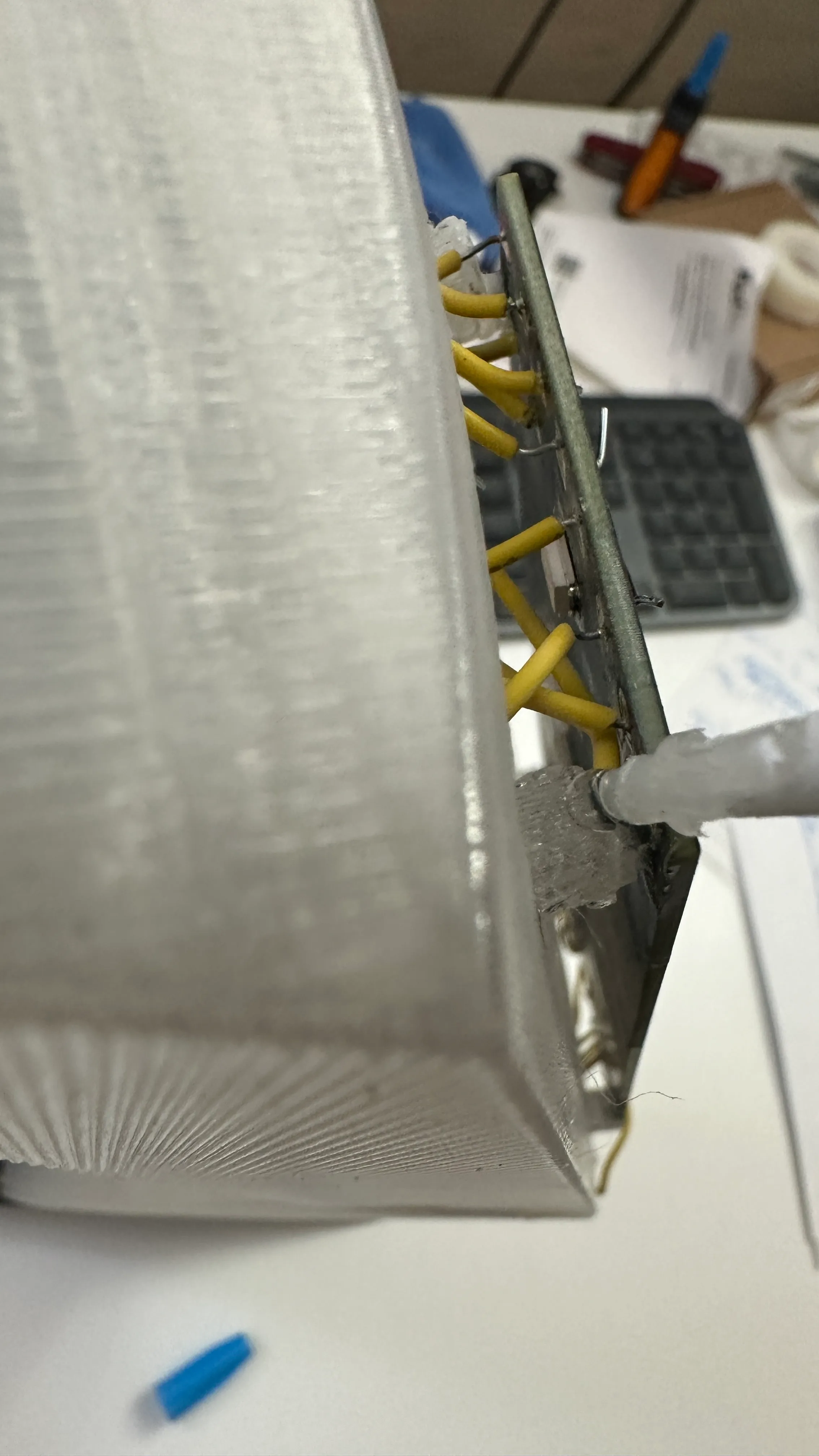
Here is an image of me in the process of glueing my pcb onto the mounts that I made in my circuit. Notice that I am no longer in the classroom because I was doing this at home the day before the field trip to finish.
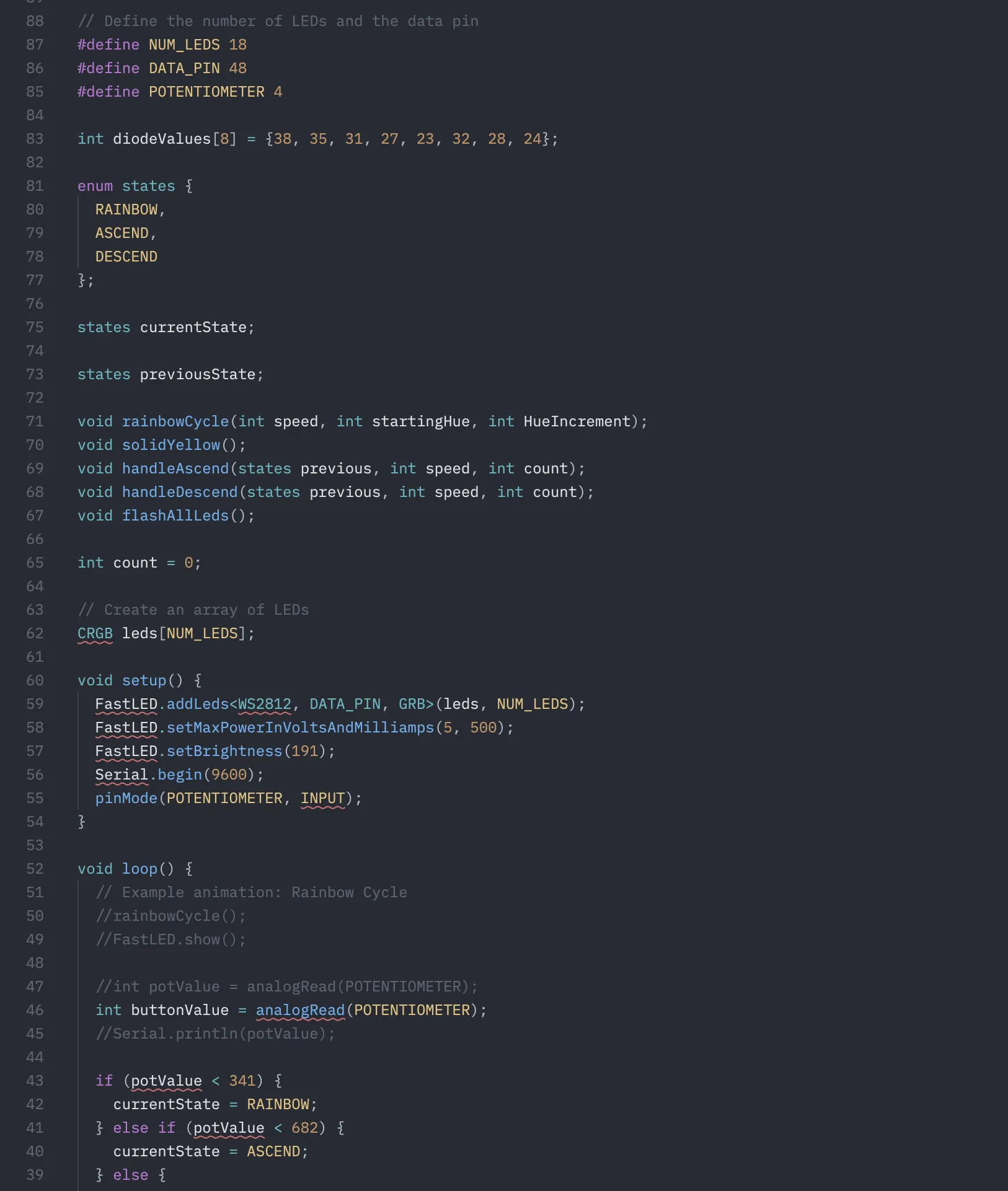
The code for the program was relativly simple for me mainly because of how much experience I have with it. The code all together took me no longer than 30 minutes to make. To drive my 18 WS2182B, I used a library called FASTLED which allowed me to individually control each LED and set the brightness and color of each. This allowed me to do cool patterns such as a RGB rainbow. On the right is a picture of my code. I did not use Arduino IDE but instead used VSCODE because I get to have better intellisense and I am able to use the ClangD language extension. So I build my code in PlatformIO which means that my looks a little different because I actually have to define functions before using it and stuff. This is not needed in the Arduino IDE because it does it for you even though its an requirement of CPP.
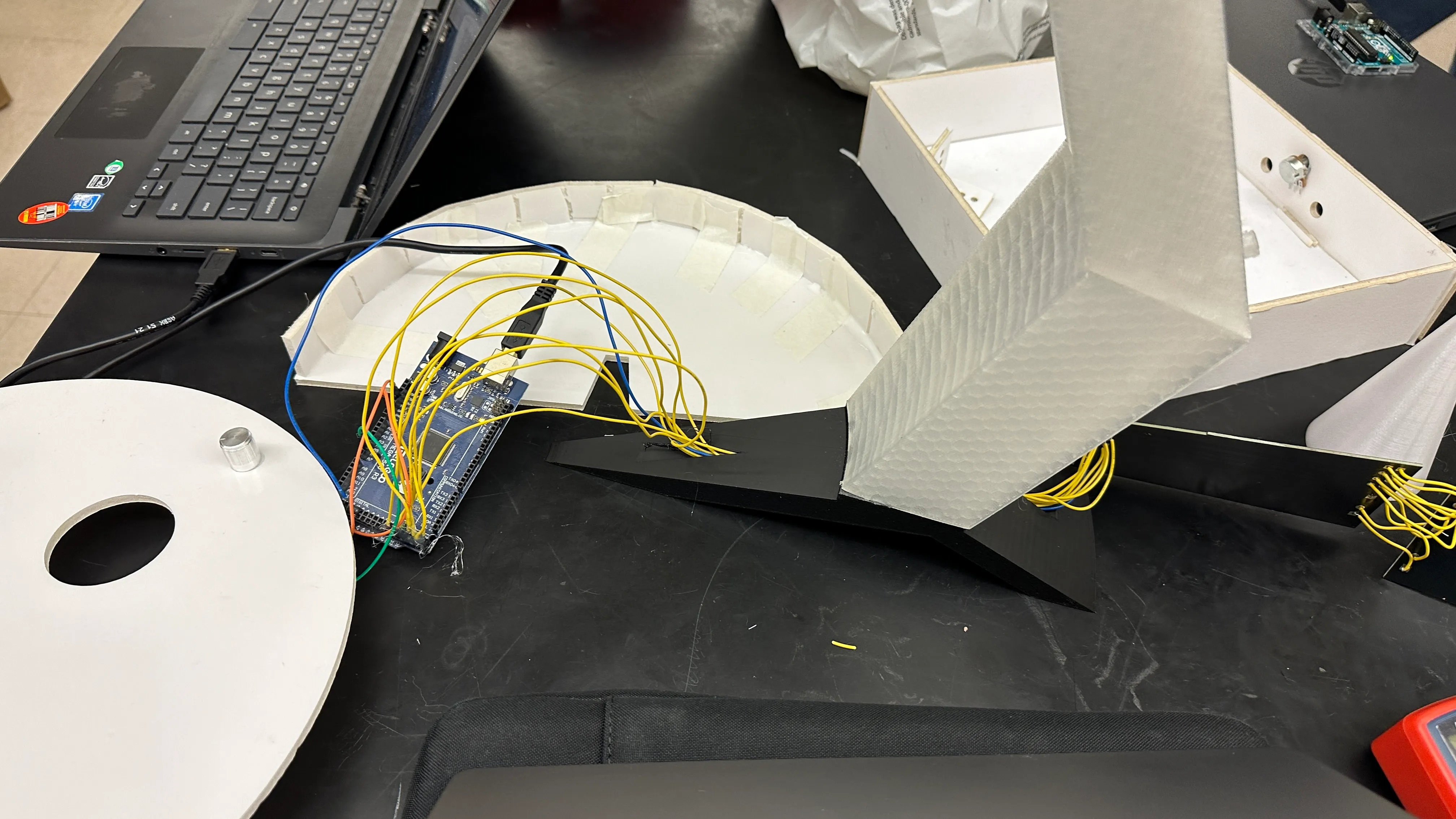
After all this, I was finished with my light sculpture. The following day after finishing, I went on BART with the class and went to demo it at the Exploratorium. Below is an video of my final work. Here you can see the code doing its work in one of the states that we programed. But when you press the button, a new sequence, of the light rising up the arm shows after which the whole thing flashes. I used a button at the suggestion of Elan instead of the potentialometer.
Reflection
Overall I really enjoyed this class and I really enjoyed making this light sculpture. There was nothing that was really challenging with the project to me which is why I tried to go above and beyond and challenge myself with stuff such as the custom pcb or 3d printing.
I did have several mistakes/troubles that I made along the way. I think the most important one was haveing my project so big that it was not able to be printed on one print. This caused more issues as I tried to split it up and individually print but also work with the time constraints. Speaking of time constraints, I should not have choosen PETG as the material that I worked with. Turns out there was transparent PLA but I did not know that until a week before the project was over. PETG is really annoying to work with as you need high print bed and nozzle temperatures. But you also have to print slowly. I think for my arm, it was estimated that the print took 7 days. You really have to baby PETG which just does not work for this project which was timed. Lastly another mistake that I made was when I decided to cheap out on my LEDs instead of buying a slightly more expensive one. This caused issues because I could not drive my LEDs at full brightness or the speed that I wanted. A related issue is that I used my own arudino, a MEGA2560 which was also a offbrand. This was a mistake as it was not able to fully and accurately time loops and was also really picky with the power supply resulting in me powering my arduino off my laptop at the museum. My biggest mistake was running out of time to print the ball, which was a really essential part of my sculpture due to the length it took for PETG to print and also because Elan was absent a week leading to this. Because Elan was not here, I could not laser cut or could not rely on being able to laser cut parts which meant that I had to 3d print it instead. My biggest goal being to have my arm stand up without falling over. But this lead to me not being able to print the ball, to make it easier to explain, I said that I forgot but in reality I was not wasting time, and was always queuing the printer.
I was able to collaborate with my classmates. When I heard that Mateo wanted to make Starship, I immediately offered to 3d print it for him so that it would look the best, and I think it looks better because it was 3d printed.
But it was not all to bad. I was able to finish my project and the diffused rgb lighting turned out really good. I am really pleased with how nice it looks up close and far away. It definitely is better than had I just decided to to use normal LEDs. I was able to quickly adapt to the 3d printer section, spliting my part into multiple parts and printing with faster PLA whenever I could, laser cutting whenever I could. My CAD when from 50 parts, when I intially sumbited the cad to 105 parts just so that I can make the part. I was able to adapt and use some foamcore to solve some production issues.