In the second unit of Honors Engineering, we learned about electronics and circuits. We also physically built circuits
- Voltage (V) is like the water pressure in the river. It represents the force pushing the electrons through the circuit, similar to how pressure pushes water through a pipe.
- Current (I) is like the flow rate of the river. It represents the actual flow of electrons in the circuit, just as the river's current is the flow of water.
- Resistance (R) is like obstacles or the narrowness of the river (rocks, constrictions, etc.). It represents anything that slows down the flow of electricity, like how rocks in a river slow the flow of water.
We started the unit by learning how electricity flows. We learned about the three concepts that is needed to conceptualize how electricity flows; the three concepts are Current, Voltage, and resistance. We used a river as an analogy to understand how it works
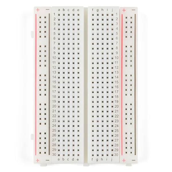
We also learned about an essential tool before starting to build circuits: the breadboard. The breadboard is where we assemble our circuits. We discovered that each side of the breadboard has positive and negative rails, which run along the length of the board, providing power across the circuit. In the middle section, the rows are connected in series, meaning each row's terminals are linked horizontally. This design allows us to create various important circuits efficiently.
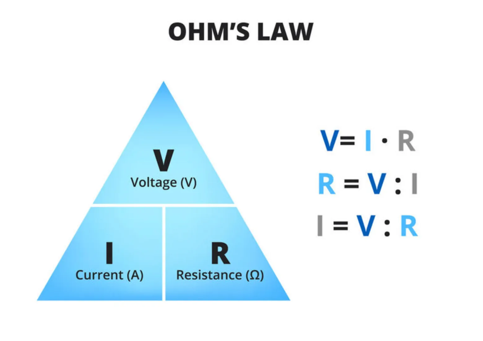
We then learned about Ohm's Law, which defines the relationship between Voltage, Current, and Resistance. Ohm's Law states that Voltage is the product of Current and Resistance, meaning that Voltage is directly proportional to the Current flowing through a circuit for a given Resistance. One practical application of Ohm's Law is preventing damage to components like LEDs. By understanding this relationship, we can avoid using a resistor that is too small, which would allow too much current to flow through the LED, potentially burning it out.
Series and Parallels Circuit
We started with basic circuits, a simple series and parallel circuit which turns on an LED or two.
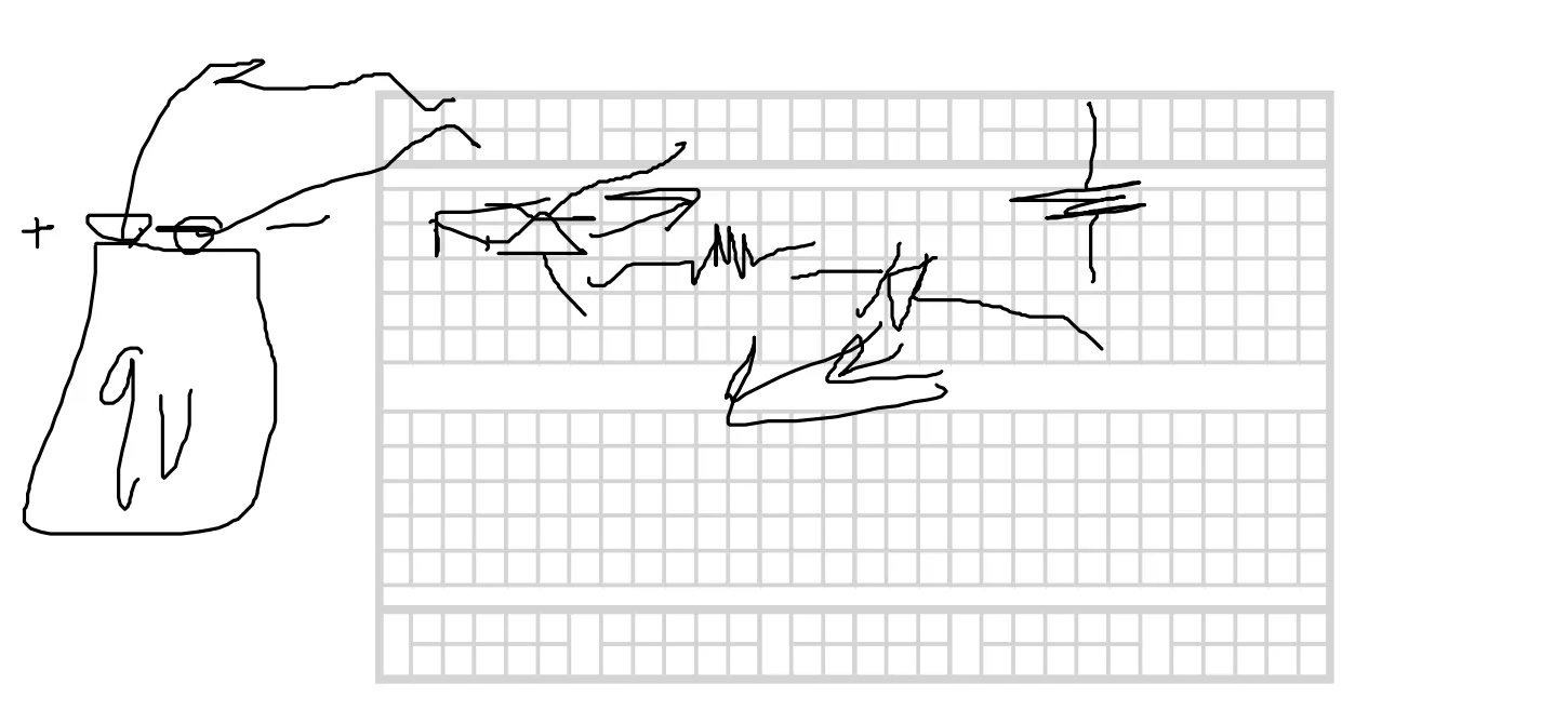
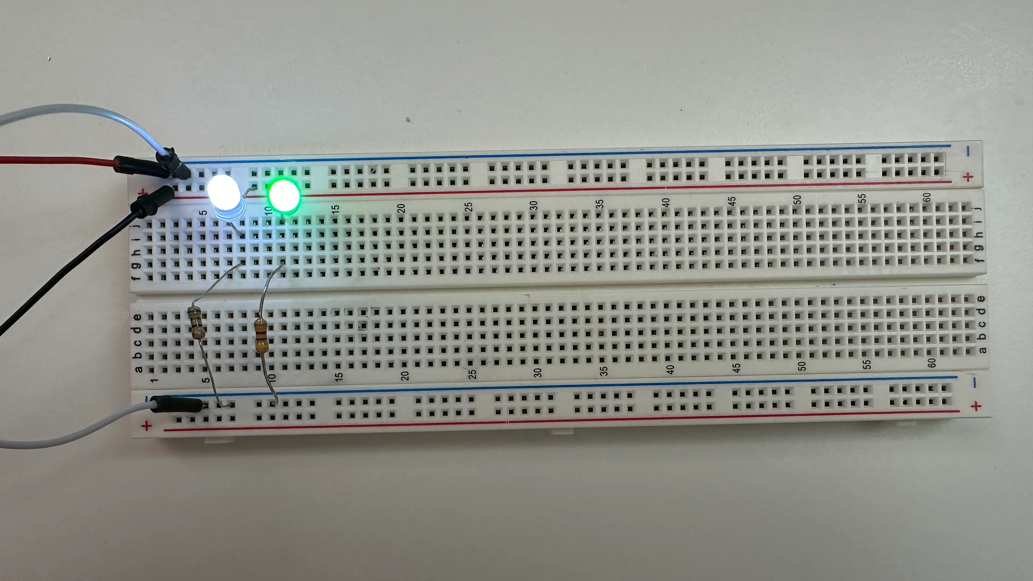
This is an example series circuit that we made. The two LEDs and the two resistors are in series to each other. This means that the sum of voltage between the two resistors should be the same as the battery, and also that the current is the same across all components of the circuit because they are in series.
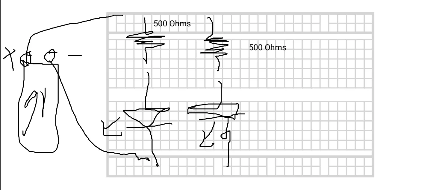
We then made a parallel circuit, which means that the two LED-resistor pairs would not be in series to each other but rather in parallel to each other. This means that the current is not the same across all components to the battery. Because each resistor-LED pair is in series to the battery, each channel should have the same sum voltage as the battery. Here is the drawing that we made of the parallels circuit.
Below I have a picture of my wired up parallel circuit. The work is done on a breadboard and you can see that there are two channels, one for each LED. If you were to remove a resistor, it would only affect one LED while the other channel would still have a lit LED.
Nightlight
We then built a more complex circuit: a nightlight. The task was to create an LED that turns on when it detects darkness and turns off when light is present. We were given the following circuit diagram to use as a reference.
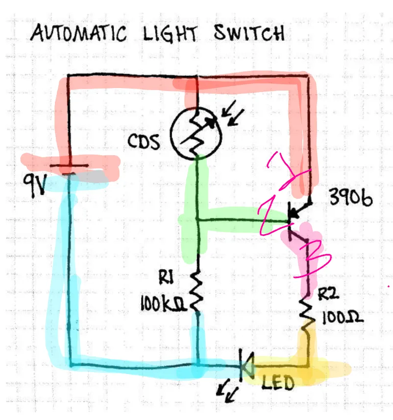
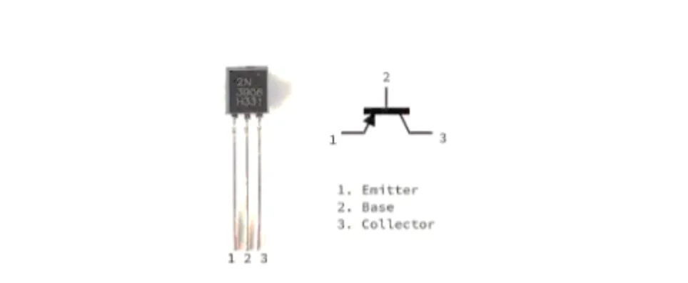
It is in this circuit that we learned about two new components, the CDS Photoresistor and the transistor. While the photoresistor might not be commonly used, the transistor is. We learned about how important a transistor is. Here is the transistor that we used.
Before assembling the circuit, we needed to visualize how it would fit on a breadboard since the circuit diagram differs from the actual layout on a breadboard. We took the provided diagram and created a breadboard illustration to better understand how the connections would work. Here’s the digital version of our concept, showing how the circuit would look when built.

We replicated the digital drawing onto the physical breadboard. Below is an image of my circuit. Note that some parts are blurred out because I was using the breadboard for multiple circuits at the time.
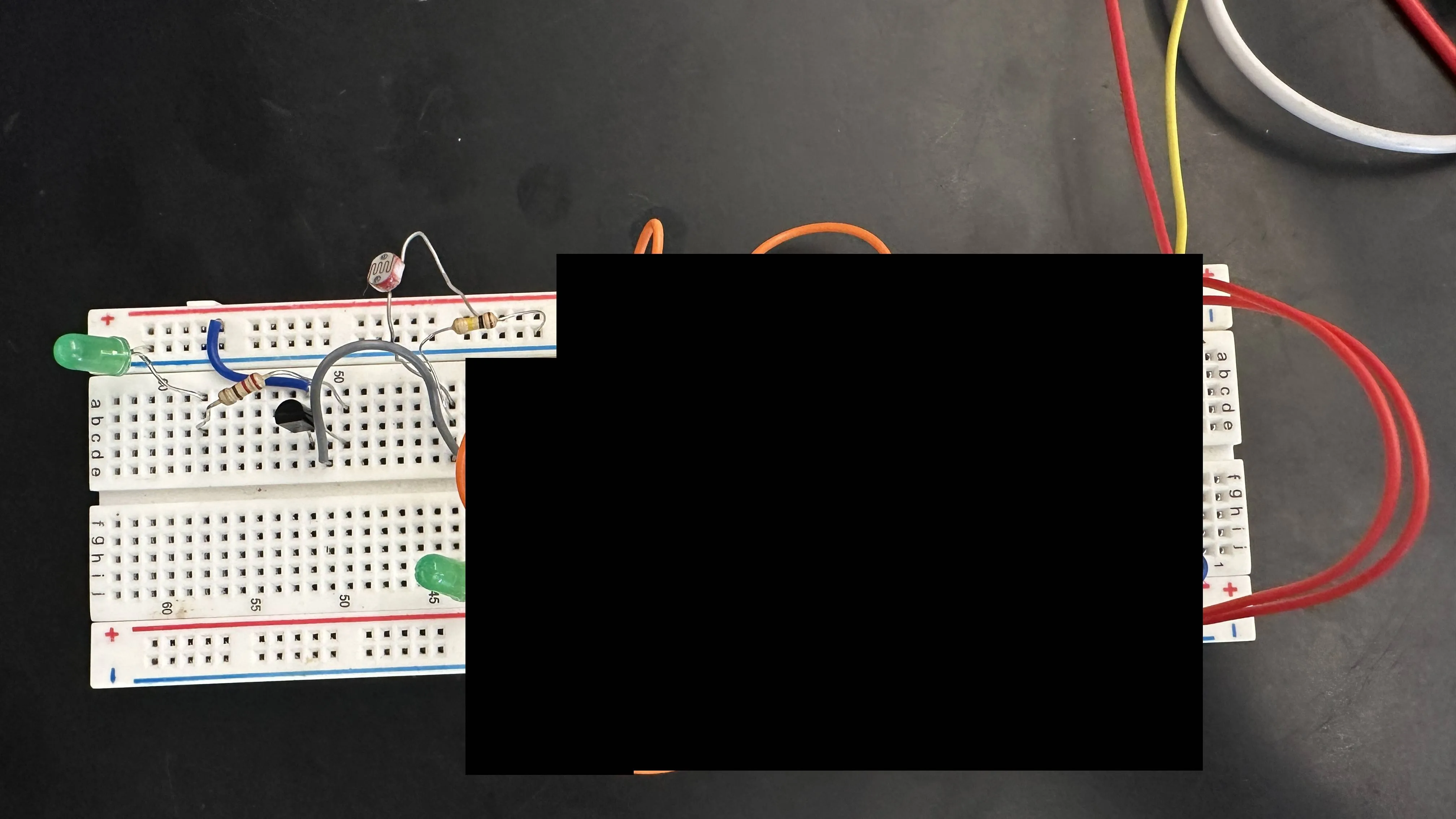
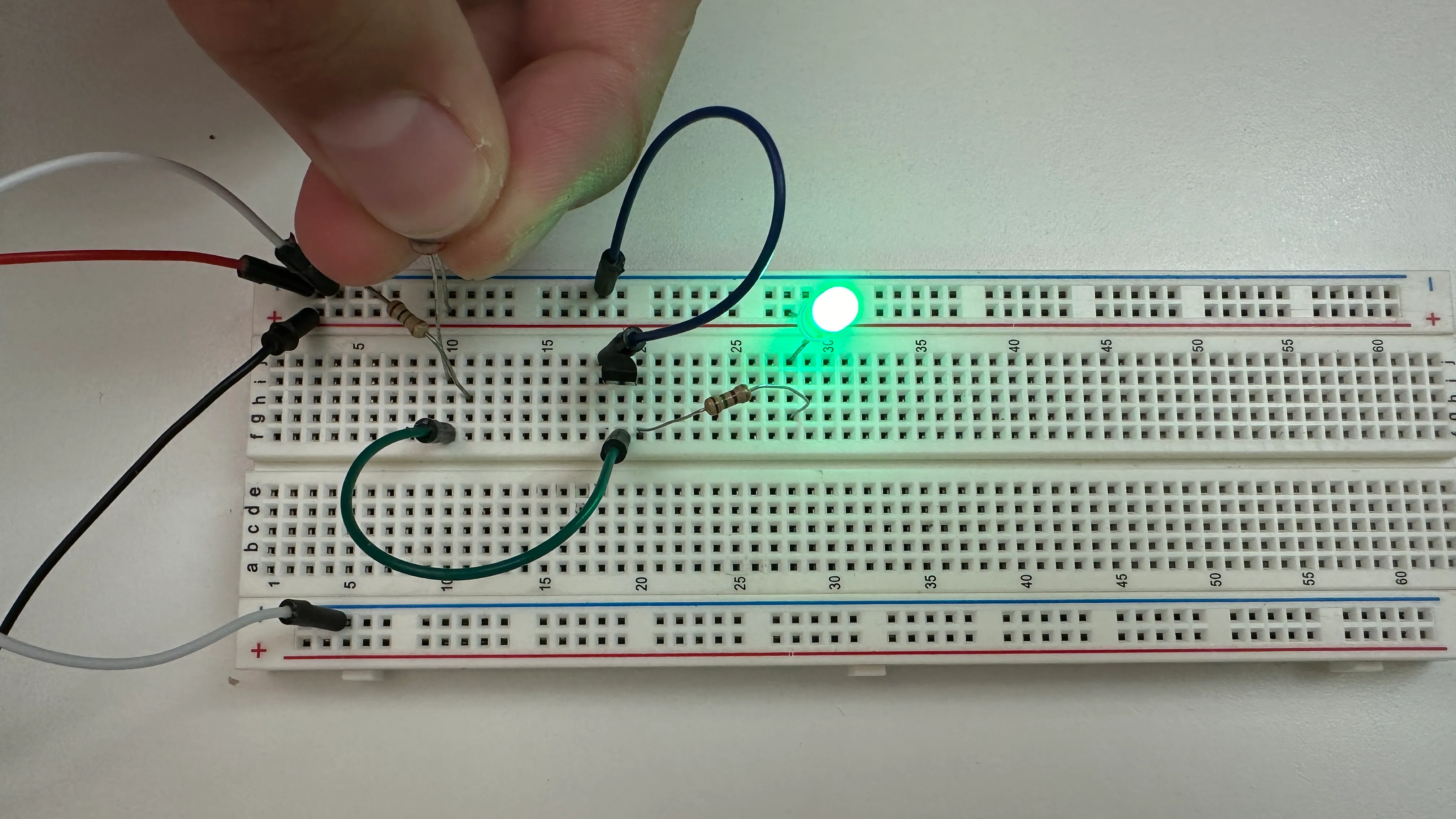
And here’s a picture demonstrating the circuit in action. When I cover the photoresistor, simulating darkness, the LED turns on, just as expected for a nightlight.
Reflection
Overall, this unit was pretty fun. I already had some experience with electronics and circuits from a previous class, so it was a nice review of the basics. For the most part, it was straightforward because of what I already knew, but I did run into some trouble getting the nightlight to work. One issue was finding the right parts, like a 100k Ohm resistor. The bigger problem, though, was that I used the wrong transistor. I grabbed a 2222 instead of the 3906 we needed. With the 2222, the polarity was reversed, so the LED would come on in bright light and turn off in the dark. Once I swapped it for the correct transistor, everything worked fine. Turns out, I wasn’t the only one who had issues— I ended up helping a few classmates troubleshoot their circuits, and a lot of them had the wrong resistor or one that wasn’t close enough to 100k Ohms.
After that, I attempted to build a more complex circuit: the blinking LED with a 555 timer. I spent several class periods debugging it but couldn't get it to work. I went through multiple iterations and even rebuilt the circuit twice, but I still couldn’t figure out the issue, which is why I didn’t include it in this update. I’m starting to wonder if maybe my parts were faulty, perhaps the 555 timer? I’m not sure how I would even check that.